Resistor
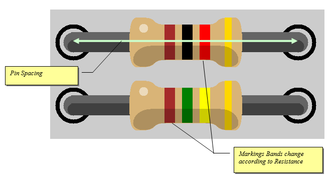
Generic resistor component models the standard axial resistor with parametric spacing and resistance color bands.
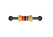
Breadboard Footprint
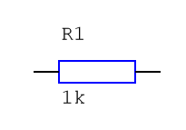
Schematic Symbol
Description
Resistors are an essential part of any electronic design but the way VBB handles resistors requires some explaination.
OHMS law is a fundamental equation linking resistance to current and voltage.
V = I x R

V = Voltage in Volts(V)
I = current in Amps (A)
R = resistance in ohms (Ω)
SPICE
The SPICE virtualization engine obey’s Ohms law and computes current’s. Supports complex voltage divider networks etc.
OpenVBB
Resistors have several mock-behaviour-modes to support many common resistor applications. The Function property is used to select the behaviour to model.
Properties
| Property | Default | Description |
|---|---|---|
| Resistance | 1k | The resistance of resistor – the color markings update according to resistance |
| Function | Fuse | OpenVBB behaviour mode markup : Fuse | | Pullup | PullDown | Wire | Open-Circuit |
Resistance
The value of the resistor resistance in Ohms. The value can have a postfix.
k ( thousands of Ohms)
M ( millions of Ohms )
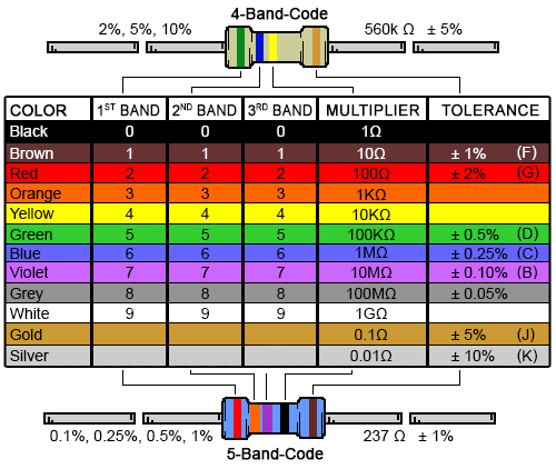
The color coding of the resistor will change to reflect the value according to the standard chart
Function
OpenVBB behaviour mode markup. Ignored when SPICE engine is used.
Fuse
In fuse mode the resistor acts as a poly fuse which if there is a short circuit will break it’s connection else it will make a wired a connection. Fuse mode is the default mode and the most versatile as it can represent a regular resitor, pullup and pulldown.
As a polyfuse when a resistor is open circuit on end of the resistor by the other end is 5V then the polyfuse is a wire and the other side of the resistor sees the 5V.
When one end is 5V and other end is 0V, a short-circuit, the polyfuse breaks and an open-circuit is created
Pullup
Pullup mode can be used for resistors that are dedicated as pullups. The main reason to use a resistor in pullup mode is when used as a basic voltage divider in conjunction with a pulldown resistor. Also there can be a minor performance improvement over using fuse mode A Pullup resistor pulls a voltage HIGH if its not driven LOW.
Note: One end of the pull-up resistor is assumed to be connected to Vdd even if its not actually wired that way.
Pulldown
Pulldown mode can be used for resistors that are dedicated as pulldowns. The main reason to use a resistor in pullup mode is when used as a basic voltage divider in conjunction with a pullup resistor. Also there can be a minor performance improvement over using fuse mode A Pullup resistor pulls a voltage LOW if its not driven HIGH.
Note: One end of the pull-up resistor is assumed to be connected to GND even if its not actually wired that way.
Wire
In Wire mode a resistor function the same as a regular wire. This can be used instead of fuse mode as there are minor performance improvement compared to a fuse
Open-Circuit
In open-circuit mode a resistor does not participate in the circuit
Useage
To illustrate how the circuit behaviour is effected by the Function of the resistor consider the above example
In open-circuit mode the circuit behaves as if the resistor is not there at all. So the voltage reported is “O/C” (open circuit ) when the button is not presed and 0.00 (GND) when the button is pressed and the switch makes contact with ground.
In wire mode the resistor acts as a zero ohm resistor. When the button is not pressed the voltage is reported as 5.00 because it is linked to Vdd. When the button is pressed a short circuit is created and actually the behaviour is undefined at that moment but the volt meter continues to read 5.00.
In pullup mode the resistor acts as you could expect. When the button is not pressed the voltage is reported as 5.00 because it is being pulled up to Vdd. When the button is pressed the resistor button pin is pulled to ground and the voltmeter reports 0.00 as expected.