DSO Basics
DSO Basics
The Digital Storage Oscilloscope (DSO) is an essential tool for visualising and analysing circuits. In this training you will learn the basic steps of adding a DSO to your project and linking it to a probe.
The DSO Design Sheet
The DSO has two elements, the DSO design sheet and logic probes. The DSO design sheet is used to visualise the signals and configure the triggers and timebase view parameters. Probes are Breadboard components and are inserted into Breadboard circuits to capture signals and are linked to the DSO to send and visualise the captured signals.
Award : Add a DSO Design Sheet to the project
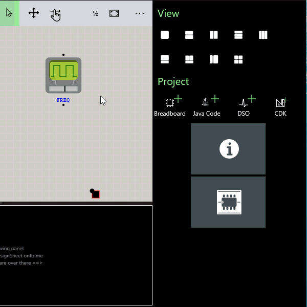
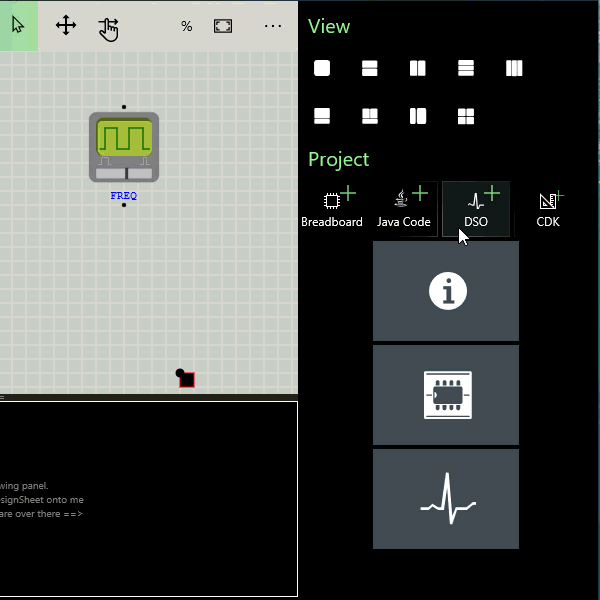
Viewing the DSO
Like all Design Sheets the DSO needs to be dragged and dropped into a view pane to actually view it. This allows different configurations of circuits and instrument views to be created and easily switched between.
Award : Drag and Drop the DSO Design sheet into the bottom view panel
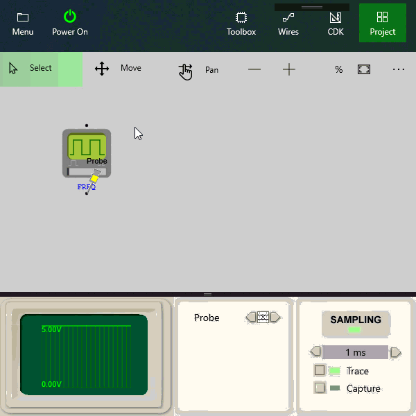
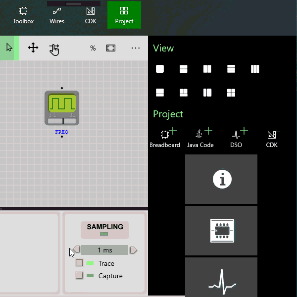
Attaching a probe
To capture signal data to display in the DSO you add one or more probes to the circuit.
Award :Add a probe and link it to the frequency generator
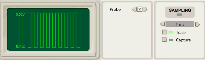
Power On to start tracing
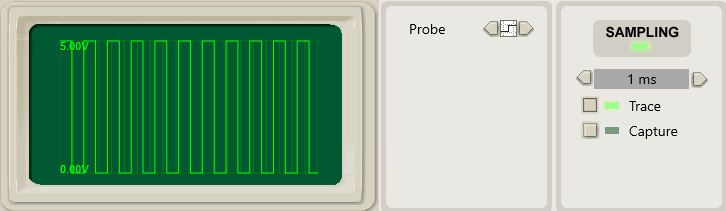
The default mode is Trace Mode which continuously captures signals with the current timebase settings. The signal sampled will be the signal shown. Without a trigger there is no specific event that starts the sampling and the signal will appear to jitter.
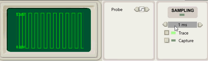
A Trigger is a specific event that the sampler waits for before it begins to sample the signal. The effect of this is to place the signal in known location on the screen allowing visual comparison with previous signals better suited for detecting signal changes.
Triggers are a property of the probes. When powered up the probes in the Breadboard are scanned and added to the DSO Triggers panel. These triggers are logically AND’d together to create a single filter trigger event
| Trigger | Event | Description |
|---|---|---|
 |
Don't care | Not used in filter |
 |
Is LOW | True if this signal is LOW |
 |
Is RISING | True if this signal is Rising Edge |
 |
Is HIGH | True if this signal is HIGH |
 |
Is FALLING | True if this signal is Falling Edge |
Award :Change the Trigger to Rising Edge to stabilise the signal
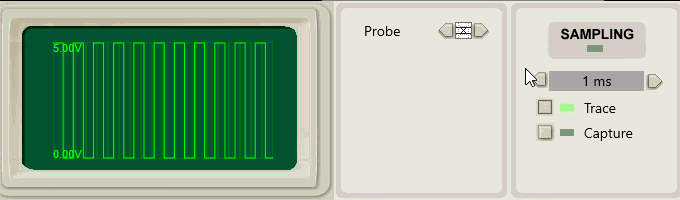
Setting the Timebase
The Timebase is the amount of time shown by each grid unit in the DSO display. Changing the Timebase has the effect of zooming in and out of the signal.
Award :Change the Timebase zooming the display in and out
Signal Analysis
The DSO is used to sample and display signals to assist in circuit analysis and troubleshooting. For example you can use it to visualise and measure the frequency generated by a frequency generator.
Exercise :Change frequency by sliding the slider of the frequency generator and visualise the signal changes in the DSO