LEDN
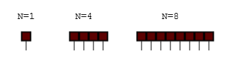
The LED component is an N array of Light Emitting Diode (LED) indicators.
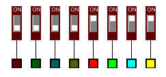
Breadboard Footprint

Description
The Nth LED is ON when the Nth input pin is driven by greater than 2.5V otherwise the LED is OFF. The color of the LED is determined by the COLOR property. When the LED is ON the LED color is lighter than when OFF giving a visual clue to voltage level at the LED input pin. LEDs are a fundamental indicator of circuit status.
The voltage is considered a Boolean HIGH/LOW and the light is ON or OFF. PWM Fading is not modelled.
SPICE
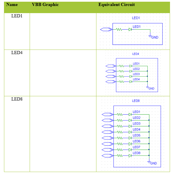
The LED Pins are modelled as a Standard Diode ( 0.7V voltage-drop ) in series with 220 Ohm resistor.
Roadmap : Parameterise the resistor and voltage-drop.
OpenVBB
The LED Pins are Input Pins where is VAnode == HIGH and VCathode == LOW the LED lights up.
PinOut
| Pin | Name | Description |
|---|---|---|
| N | Output[N] | DIP Output. Nth Pin is 5V if the Nth switch is On State else is Gnd. |
Properties
| Property | Default | Description |
|---|---|---|
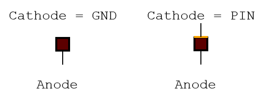
| Cathode | Ground | Determines how the cathode is connected |
| Color | red | The color of the LED indicator |
| PinCount | 1 | The number of pins. |
Useage