Interactive
Interactive Circuits
Virtual Breadboard circuits are interactive. Input components such as buttons, switches and potentiometers are used to provide user input to test and operate virtual circuits.
Push a Momentary Button
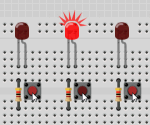
The momentary button is normally not connected contact switch. When you press the button a contact is made between pins on either side of the button completing a circuit while the button is held down.
Award : Power On  the circuit then locate the momentary button. Press and hold it down for a few moments. The L.E.D will light up because the momentary contact switch completes the L.E.D circuit with the battery and resistor.

Toggle a Switch
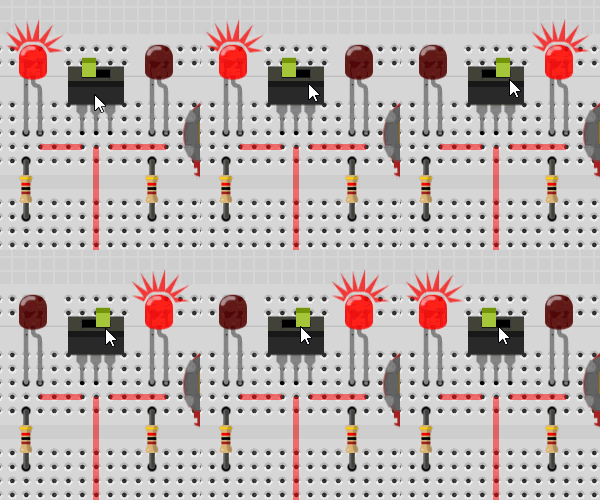
A 3 pin switch has two possible configurations. It can connect the command center pin with the left pin or the right pin. When connected to one pin the other pin is disconnected or open circuit. The switch position toggles to show which pin is connected to the center pin.
Award : While Powered Up locate the Toggle Switch and click the component on the switch location. The position of the switch slider will toggle and the alternate circuit will be completed toggling which L.E.D is activated.

Rotate a Potentiometer
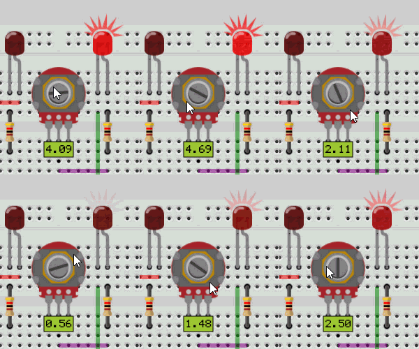
A potentiometer is a variable resistor which when you rotate the dial it’s resistance changes which changes the output voltage of the central pin. Virtual Breadboard models the voltage output of the potentiometer voltage divider which can be read by instruments like the digital voltmeter and visualised by components like the L.E.D which are sensitive to analog voltage levels.
Award: While Powered Up locate the Potentiometer and press and hold the mouse down on the potentiometer dial. Rotate the dial around the center for the full range of voltage values. To receive this reward you need to exercise the full potentiometer range. You will see the L.E.D dim when the voltage is low and brighten when the voltage is high.

Advanced TIP: VBB is not an analog PSPICE simulator but instead models high level circuit behaviour. For example a PSPICE simulator will model the reduced L.E.D current and bandgap and deduce the L.E.D should dim but VBB models common circuit behaviours directly.