NodeMCU ESP8266
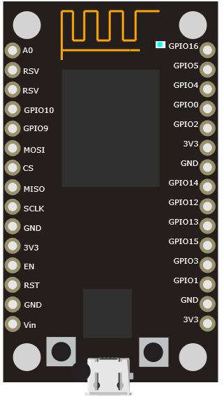
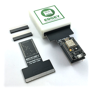
VBB EDGEY Avatar Breakout with NodeMCU ESP8266 footprint.
Breadboard Footprint
Schematic Symbol
Not available > Roadmap: Bind schematic.
Description
The ESP8266 device is connected with the USB pointing away from the EDGEY when connected. The pass-thru header pins can be used to connect to components on a physical breadboard at the same time as Virtual Components hosted in Virtual Breadboard.
PinOut
Pin |
Name |
EDGEY |
Description |
|---|---|---|---|
1 |
A0 |
DAC |
Analog Input |
2 |
RSV |
Reserved |
|
3 |
RSV |
Reserved |
|
4 |
GPIO10 |
SDIO Data 3 - Reserved for ESP82666 FLASH |
|
5 |
GPIO9 |
SDIO Data 3 - Reserved for ESP82666 FLASH |
|
6 |
MOSI |
MOSI* |
SDIO Data 1 - Reserved for ESP82666 FLASH |
7 |
CS |
CS* |
SDIO CMD - Reserved for ESP82666 FLASH |
8 |
MISO |
MISO* |
SDIO CLK - Reserved for ESP82666 FLASH |
9 |
SCLK |
CLK* |
|
10 |
GND |
Ground |
|
11 |
3V3 |
3V3 Output |
|
12 |
EN |
Chip Enable (Active High) - EDGEY : Reset |
|
13 |
RST |
Reset |
Chip Reset (Active LOW) |
14 |
GND |
Ground |
|
15 |
Vin |
5V Input to 3.3V Regulator |
|
16 |
3V3 |
3V3 Output |
|
17 |
GND |
Ground |
|
18 |
GPIO1 |
IO/TX* |
|
19 |
GPIO3 |
IO/RX* |
|
20 |
GPIO15 |
IO |
|
21 |
GPIO13 |
IO |
|
22 |
GPIO12 |
IO |
|
23 |
GPIO14 |
IO |
|
24 |
GND |
Ground |
|
25 |
3V3 |
3V3 Output |
|
26 |
GPIO2 |
IO |
|
27 |
GPIO10 |
||
28 |
GPIO4 |
SDA |
|
29 |
GPIO5 |
SCL |
|
30 |
GPIO16 |
IO |
[*] See Errata
Properties
Property |
Values |
Description |
|---|---|---|
COM | EDGE |
The serial port to connect to the Arduino Host |
|
9600 |
The baud of the Arduino serial passthrough |
|
… | Python App* |
The micropython App to download at runtime |
|
COM |
The COM port of the attached NodeMCU device |
Connection
The EDGEY serial port COM connection is slected by drop-dropdown
Serial Baud
Serial Baud is the communication speed that should be used when calling UART(baudrate=9600, in the MicroPython application. The Avatar will listen to the RX/TX pins and pass-through the serial it is wired up to a UART device in VBB.
NOTE: The UART is shared with REPL on this device
Py App
When using the built in Python Editor you can link the Python source code by linking it with the Py App drop down. Use <code>…</code> when developing in disconnected mode.
Node MCU USB
The COM port that the NodeMCU device is connected to. Select the device from the drop down. If you associated the COM port with VBB it will have to detach from other tools such as Thonny or serial terminal for it to work.
Useage
Disconnected Mode
You can develop for NodeMCU with any platform in which case you use the Avatar in disconnected mode.
Set Py App to ..
Set Pico USB to ..
Integrated MicroPython Mode
When developing with Micropython
Add a Python App from the Project Ribbon. The default name is PyApp.
Select the newly added App from the Py App dropdown property
Select the correct COM port from the NodeMCU USB from the drop
The Python application will be downloaded automatically using REPL when the application starts
NOTE: The reference examples use MicroPython and many use libraries assumed to be preinstalled using Thonny or similar from the libraries repository.
https://github.com/virtualbreadboard/vbb-micropython
Notes
Available pins are: 0, 1, 2, 3, 4, 5, 12, 13, 14, 15, 16, which correspond to the actual GPIO pin numbers of ESP8266 chip.
Errata
SPI - Revision 1 has the SPI mapped to the default SPI pins rather than the hardware HSPI pins. Since the default SPI is used to access the onboard flash SPI is not usable in Rev1. A Rev2 version will be sent to everyone who has purchased Rev1 when it becomes available.
UART - the uart is shared with micropython REPL making it difficult to multiplex when using micropython.

