Sample and Multiplex
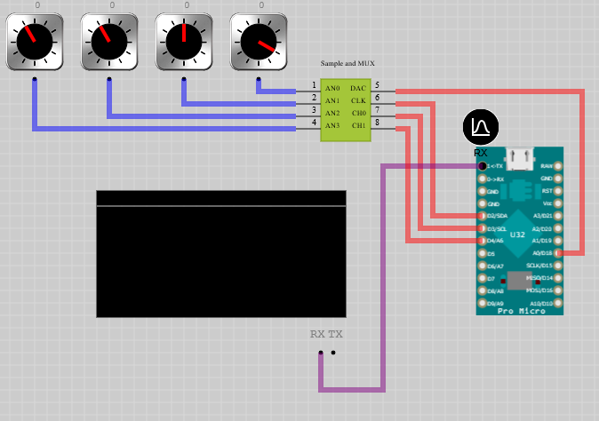
Multiplexes multiple analog channels into a single analog channel.
Toolbox

Breadboard Footprint
N-A
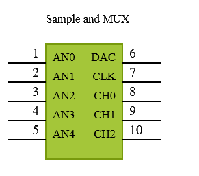
Schematic Symbol
Description
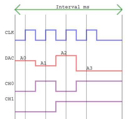
Periodically samples very Interval milliseconds Channels analog channels and encodes the values on a single DAC pin using a CLK pin and a binary representation of channels. On a rising CLK edge the value of channel is available on the DAC pin. Between Samples there are Channels transfers.
Pin Out
| Pin | Description |
|---|---|
| AN | The number of input pins |
| CLK | The output CLK |
| DAC | Axis pins are dynamically created to collect sample data |
| CH0.. | Data label pins are dynamically created to markup submitted sample data sets |
Analog Pins
The AN analog pins are dynamically added by setting the number of Channels properties. All the channels are sampled at the interval period and then multiplexed over the single analog channel.
CLK Pin
The CLK output pin transfers multiplexed value on the rising edge. The next DAC value and channel bits are setup on the falling CLK falling edge.
DAC
The sampled input AN are encoded into a DAC output. When using the physical EDGEY series the DAC resolution is 8-bits.
Channel Output Pins
The current channel encoded in the DAC value is represened by a binary value encoded on the CH0.. output pins.
Properties
| Property | Default | Description |
|---|---|---|
| Channels | 2 | The number of input channels to multiplex. |
| Interval | 100 | An integer number of milliseconds between samples |
Channels
The number of input channels channels.
Interval
An integer number of milliseconds between samples.
Usage