Schematics
Schematics
Schematics are abstract representations of physical components. It can be easier to understand how a circuit functions when represented in schematic format. Often schematics are used to describe a circuits netlist in a separate design step. In Virtual Breadboard (VBB) Schematics and Breadboard components are merged into one design sheet creating hybrid designs where all the information about the design is in one place.
Components with the same ID are linked
Components have schematic/breadboard representations
When a circuit has a schematic and breadboard component with the same ID the schematic component creates the netlist for the breadboard component.
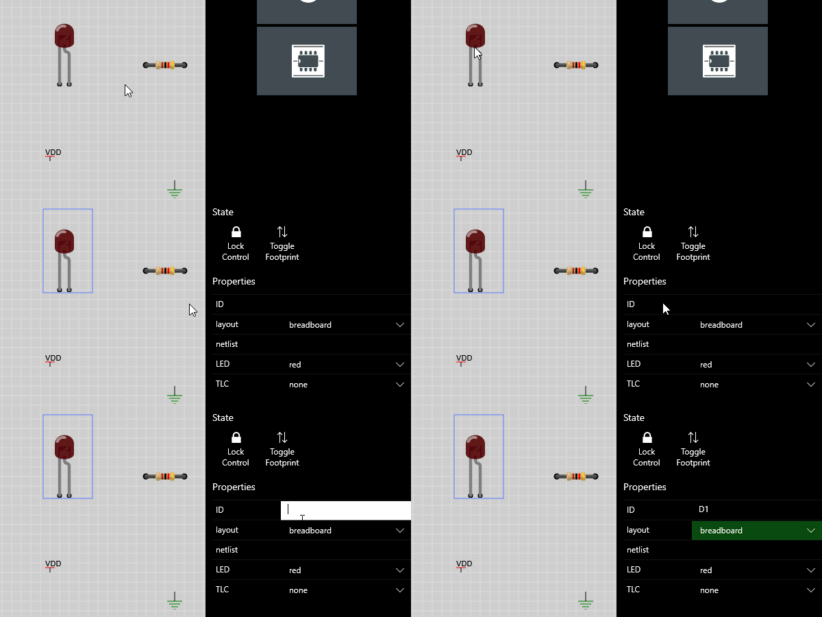
Edit ‘ID’ property
When a component shares the same ‘ID’ property the pin the pins of both components are linked with virtual links.
Award : Edit the property of the LED to be D1
Common ‘ID’ Common Netlist
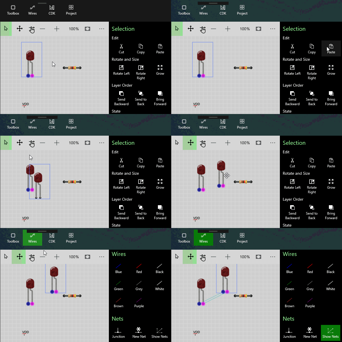
Components with the same ID share a netlist between them. To see this copy and paste a component with the same ID and Show the Nets to see the hidden links between the components.
Exercise: Duplicate LED D1 and Show Nets
Edit ‘Layout’ property
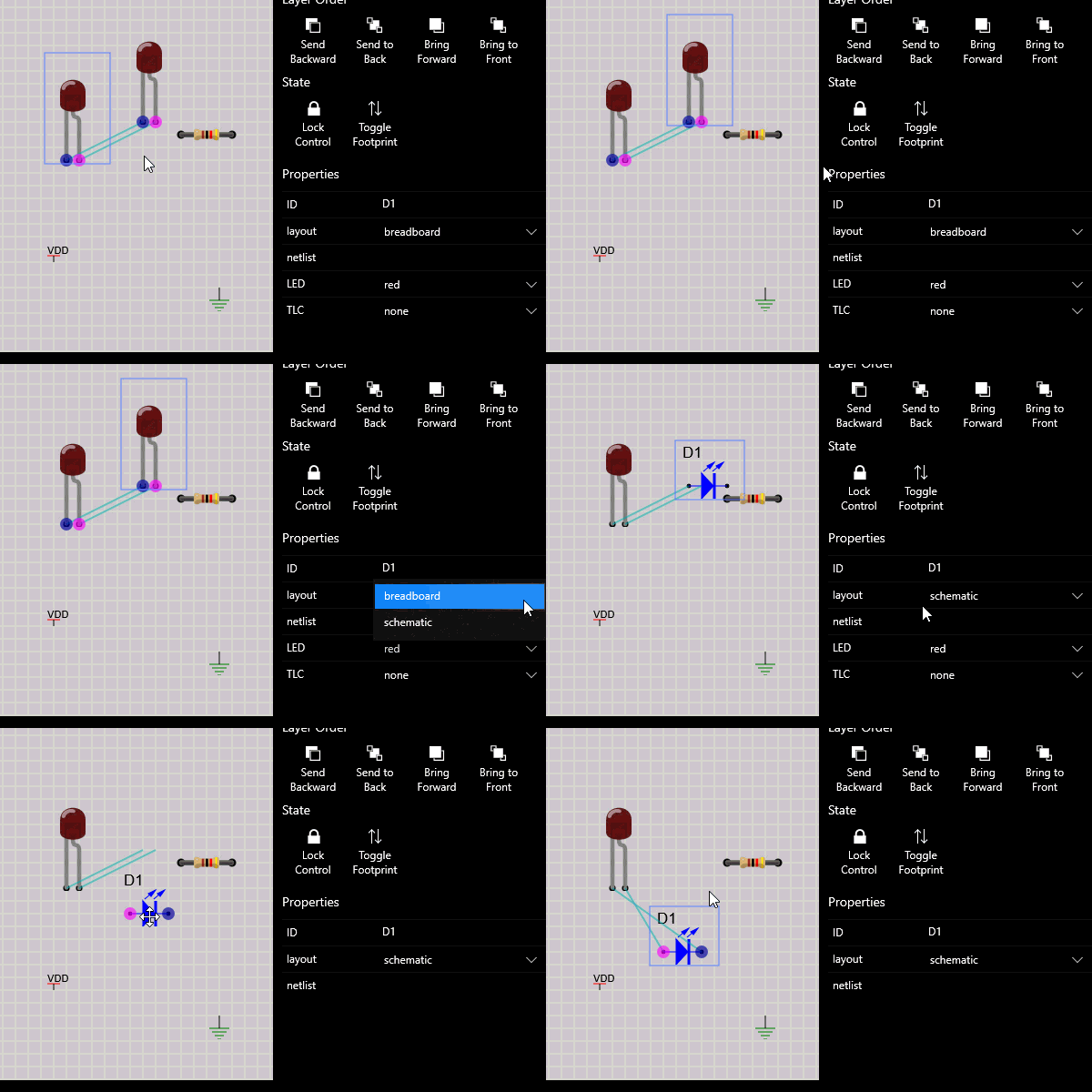
The Layout property determines which type of view of the component is rendered. So far you have only seen the Breadboard layout. Many components also support a Schematic layout.
Award: Select the duplicate LED and set it’s layout property to Schematic
Exercise : Repeat the previous steps
Repeat the above steps for the Resistor * Edit the Resister property to be R1 Copy and Paste the Resistor Set the duplicate Resistor layout property to be Schematic
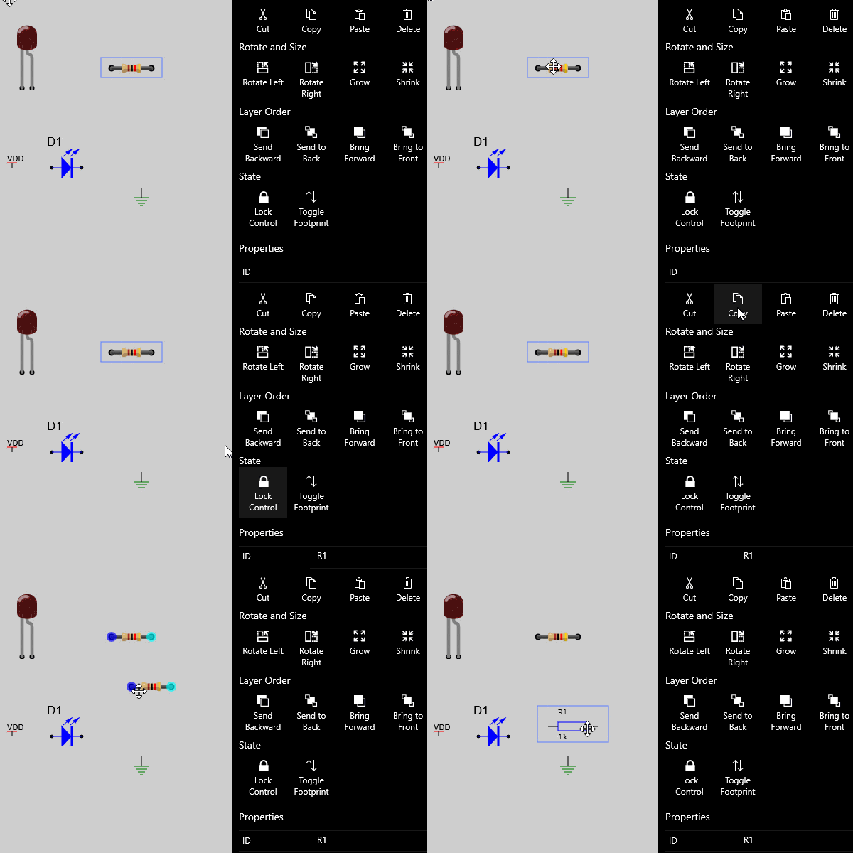
Wire Up the Schematic
When the schematic twins are wired to form valid circuits the matching Breadboard component twin is also wired with the same netlist.
Award: Snap the schematic elements together to form a powered LED circuit
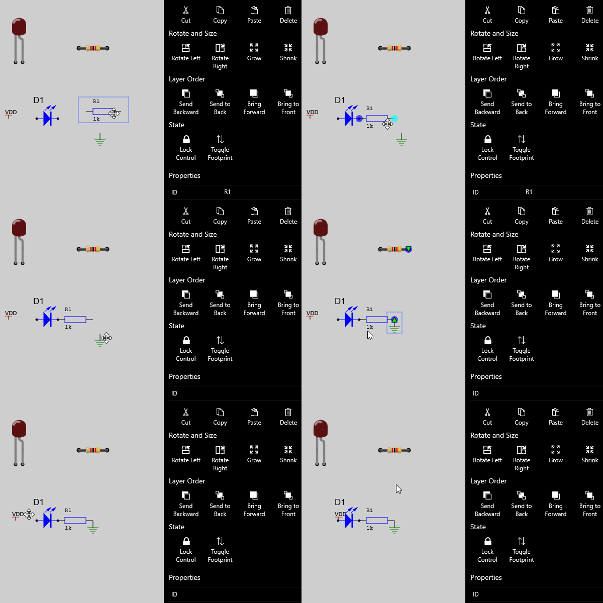
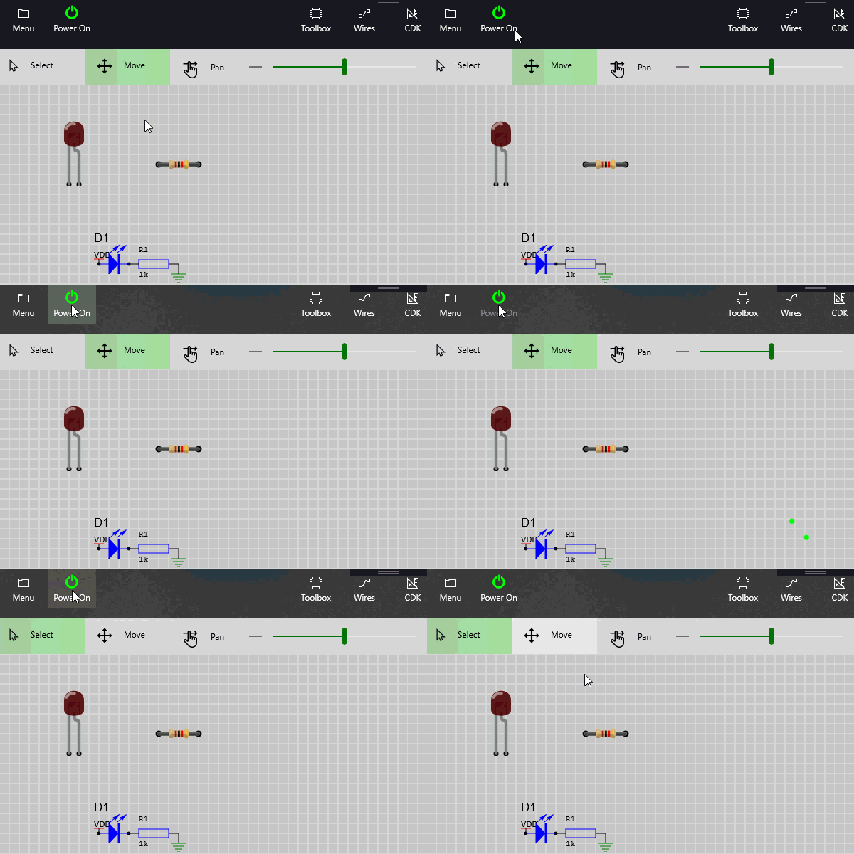
Exercise : ‘Power Up’ and verify
At runtime only the Breadboard component is activated. The schematic component can be used to create an understandable netlist but it does not participate in the runtime circuit.
Note: One advantage of this approach is the physical Breadboard components can be placed anywhere without the confusion of connecting wires running all over the place.
Exercise: ‘Power Up’ the circuit and verify the LED brightens as powered by the virtual links.
